Experiments in Ray-Tracing, Part 7 - Multi-Threading
This is a very old article, included for historical interest only!
Now that I’ve covered the basics of ray-tracing, I’ll cover a few optimization techniques I’ve tried. Optimizations can be placed into three broad categories:
- Those which speed up the ray-tracing, without affecting the image;
- Those which speed up the ray-tracing, but degrade the image quality, and;
- Those which improve the image quality, but slow down the ray-tracing.
Obviously implementing the first set of optimizations is a no-brainer, but which blend of the others is of course up to you.
So let’s start with the most effective speed-up: multi-threading. Rendering each pixel in the image happens pretty much independently of the others, so we can partition the rendering amongst the available processors (or cores).
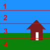
One naive way of partitioning the scene is to simply divide it into N parts, assuming we have N processors. This however doesn’t necessarily make best use of the processors: if one of those partitions has less complexity than the others, then that processor will be idle for most of the render.

In this example, we’ve partitioned the rendering of a scene amongst four processors, but the first slice will finish way before all the others, since it contains nothing but background colour. Slice three will probably finish last. Essentially, we have a very uneven usage of our CPUs.
A better way to use the available processors is to divide the rendering into many more parts than we have processors, and put them in a work queue. Each processor can then pop a piece of work from the queue every time it’s ready. When the queue is empty and all processors are done, then the rendering is complete. This method makes far better use of the available CPU power.

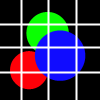
In fact, we can be even more cunning with our division of the scene. Suppose we divide the scene displayed here into a grid. Each grid line corresponds to a plane passing through the camera. (If you have trouble with that idea, consider the edges of your monitor: you can imagine triangles with points at your eye, and two points on the corner of the monitor).
We can work out which spheres (yes, those coloured circles are supposed to be spheres) intersect each column (left to right):
- Red;
- Red, Green, and Blue;
- Red (just), Green, and Blue;
- Blue.
Similarly, we can work out which spheres intersect each row (top to bottom):
- Green;
- Green and Blue;
- Red, Green (just) and Blue;
- Red and Blue.
(See last article for a selection of intersection tests).
To speed up this pre-processing stage, I used a binary chop algorithm - repeatedly partitioning the scene into two sets of objects.
Once we’ve performed this pre-processing, we can make use of this information to speed up the actual processing. When rendering each part, the primary ray intersection test only needs to consider those objects which are in the intersection of the appropriate row and column sets.
As an example, consider the top-left part. The row contains the green sphere; the column the red sphere. We can therefore see that the area doesn’t contain any objects - so there’s no point rendering each pixel - we just fill it with background.
For parts that do contain one or more objects, we can speed up primary ray intersection testing by only testing against the identified objects - we don’t need to test against every object in the scene.
Published: Sunday, August 17, 2008
You may be interested in...
Hackification.io is a participant in the Amazon Services LLC Associates Program, an affiliate advertising program designed to provide a means for sites to earn advertising fees by advertising and linking to amazon.com. I may earn a small commission for my endorsement, recommendation, testimonial, and/or link to any products or services from this website.